I was hired to build a new PC for an industry friend because her old one just died. She’d brought it to two computer repair shops, but they couldn’t fix it, so she decided to invest in a new machine instead. The old one was due for an upgrade anyway – Ryzen 7 1700X on a Gigabyte AORUS GA-AX370-Gaming 5, and virtual instruments are not getting any smaller these days.
The Challenge
But since I like a challenge, and after dabbling with electronics for a while – lately getting into the whole VHS adventure which had me soldering test points inside a VCR to extract RF signals – I thought: “Let me take this motherboard with me and I’ll see what I can do. Best case scenario – you get your motherboard back, and we can potentially build a backup/NAS machine from your old trusty workstation.”
She agreed. I remember going back home with the motherboard in a box in my backpack, thinking “I wonder how broken it actually is.” There have been situations where people sell their “broken” stuff for dirt-cheap, only for the tech-savvy buyer to discover they (a) weren’t actually broken in the first place, or (b) there was indeed something wrong, but nothing an experienced person couldn’t fix themselves.
First Order of Business: Observe and Document
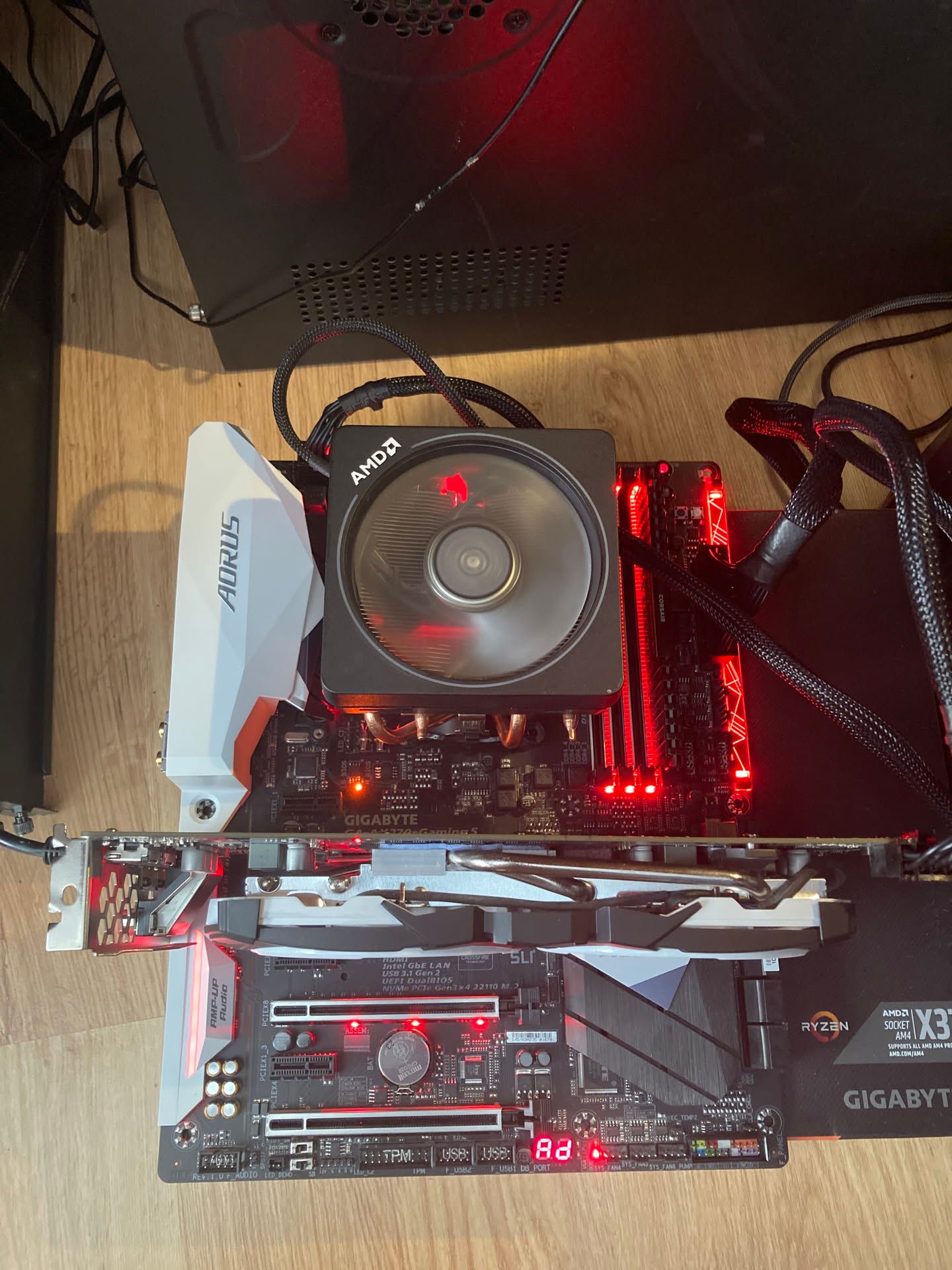
I took the motherboard out of the box, cleaned it with compressed air, set it up on a workbench, and installed my old Ryzen 2700X with AMD Wraith Prism cooler, Radeon RX580, and one stick of Corsair Vengeance DDR4. Plugged in my spare EVGA Supernova G3 power supply to see if it would boot.
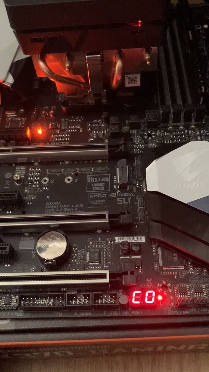
No dice. The two-digit display on the motherboard showed some different codes and stopped at C0, along with the red CPU LED. Interesting.
Let’s see what happens when I remove the 8-pin CPU 12V connector.
Okay, we get 00 – which I believe is correct, as the CPU can’t initialize without power.
Let’s check the whole sequence of codes displayed before the C0. It’s too quick for the naked eye, but not too quick for my phone’s high-framerate recording.
00 → FC → 3E → 90 → 14 → 15 → 14 → 15 → C0
Then the sequence repeats on the selected BIOS chip, then repeats again on the OTHER chip, and finally stays stuck at C0.
Aaaaaaand… We're stuck.
Both B_BIOS and M_BIOS LEDs stayed solid – no flashing. The same exact behavior occurred whether booting from M_BIOS or B_BIOS, so they were equally broken.
Understanding the Dual-BIOS System
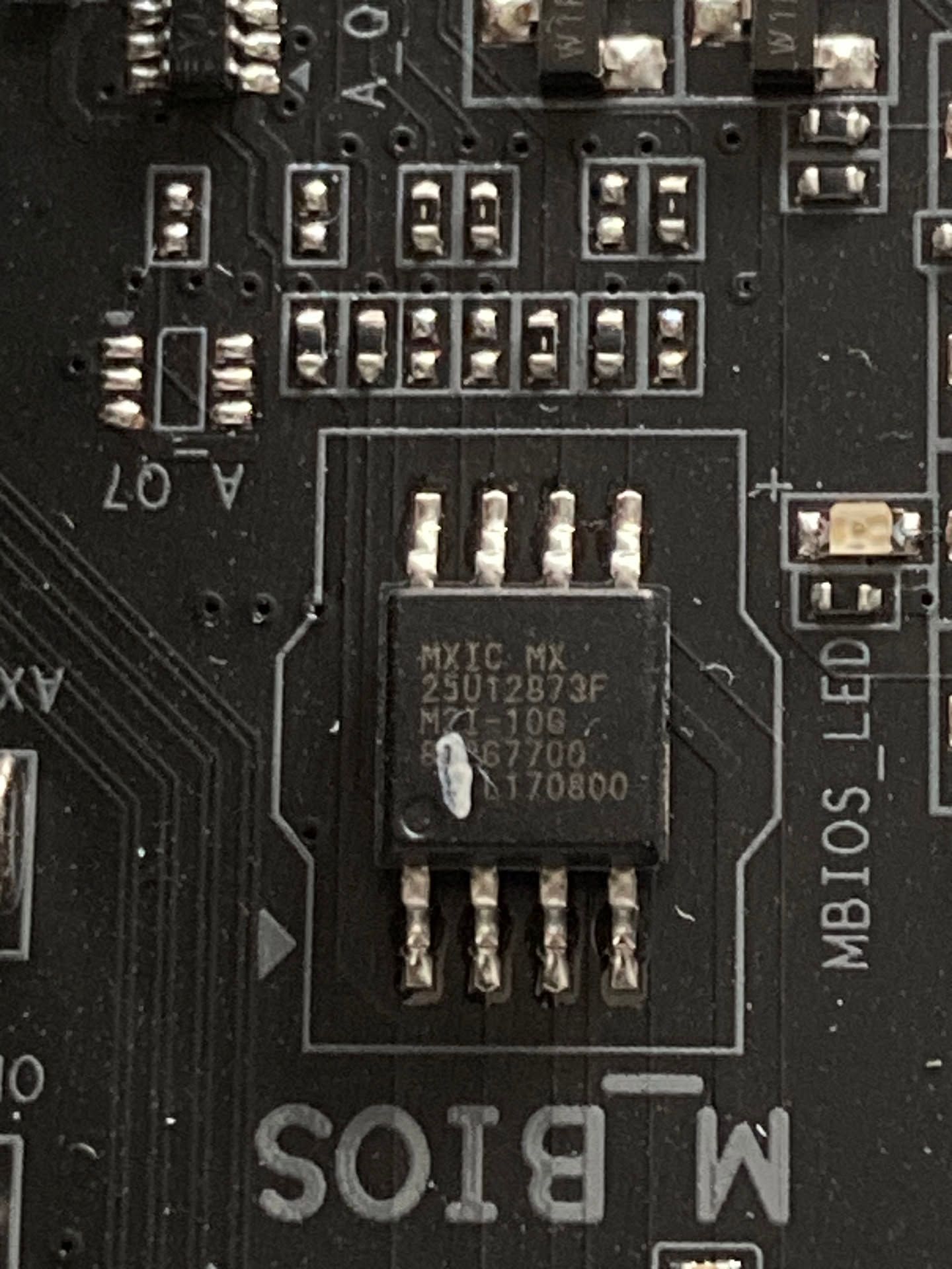
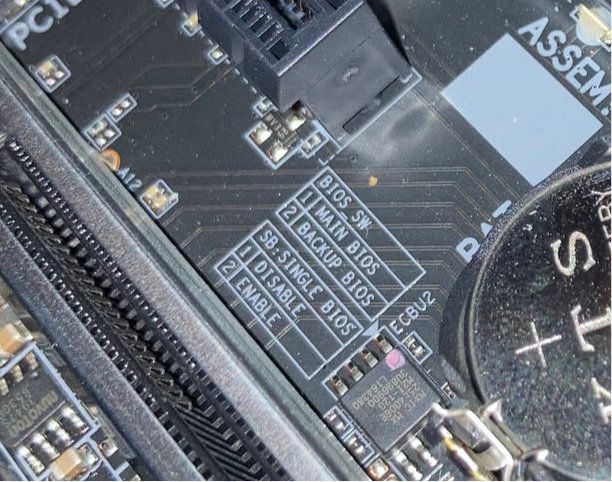
The Gigabyte AORUS GA-AX370-Gaming 5 has Gigabyte’s patented DualBIOS™ feature with two switches to configure it. In a nutshell – you have two physical Macronix MX25U12873FM2I-10G chips, each with 128Mb (16MB) of storage holding the BIOS. If there’s ever a failure due to corruption, hardware malfunction, improper OC settings, or power failure, you can recover from the second chip.
To do so, you’d either let the motherboard handle it automatically when the switches were set up with DualBIOS™ enabled, or you could flip the switch to disable that feature and choose exactly which chip to use for booting. If you knew M_BIOS was corrupted, you could just run on B_BIOS until M_BIOS was fixed.
DualBIOS™ Switches
Or so the theory went.
Here we go, decoding that sequence (based on AMI BIOS POST codes for AM4 platforms):
00 = Not used / Initial state
FC = Reserved code
3E = Late PEI initialization (Pre-EFI Initialization)
90 = Beginning of memory initialization
14 = Pre-memory SPD detection
15 = Memory presence detect / SPD reading
C0 = Memory initialization failure / Memory training failed
Troubleshooting Hell
I tried everything:
All combinations of the two BIOS switches – no boot, C0 error
Unplugging the 8-pin CPU power – no boot, 00 error (expected)
Clearing CMOS – no change
Testing every RAM slot (DDR4_1, DDR4_3, DDR4_2, DDR4_4) – no change
Removed the CMOS battery, cleared CMOS by shorting the pins for 30+ seconds, drained residual power by pressing the power button multiple times, left the battery out for 10 minutes. The old battery showed 2.73V on the multimeter; the new one was 3.31V. Still no change, so I put the old one back in.
Removed the CPU, cleaned both the socket and pins with 99.9% IPA, let it dry for 30+ minutes, reseated the CPU – no change
Visually inspected the VRMs and everything around the CPU, including the socket and CPU itself – no discoloration, no residue, no bulging, no visible damage, no bent pins, no blocked socket holes
PSU is fine – I used it daily with my main machine, now I use it with my homelab, and it’s a 80+ Gold unit, a real workhorse.
Critical Analysis
This is NOT a CPU problem or early POST failure. The sequence shows:
CPU is initializing properly (past code 3E)
System is reaching memory initialization (90)
System is attempting to read RAM SPD data (codes 14/15)
System is failing at memory training (stuck at C0)
The fact that it cycles through 14 ↔ 15 multiple times means it’s trying to detect/read the RAM, having trouble with SPD communication or memory training, then giving up and showing C0. Both BIOS chips showing identical behavior suggests the chips themselves are either fine (just outdated/incompatible) or were corrupted and needed a fresh BIOS. In case of my configuration, this is likely a RAM compatibility or memory controller issue.
The X370 RAM Compatibility Problem
Here’s the harsh reality about early X370 boards and things they struggled with:
High-density RAM (16GB dual-rank single sticks)
Speeds above 2666MHz
My RAM: Corsair Vengeance LPX 3000 CL15 16GB – almost certainly using Hynix AFR or Hynix MFR chips. These were problematic on first-gen Ryzen/X370. B450 handled them fine; X370 often didn’t.
Worth noting: on my previous board (ASUS ROG STRIX B450-F GAMING), this exact combo of R7 2700X and Corsair Vengeance LPX 3000 CL15 worked from the get-go but the ASUS motherboard was around a year older, so it had a little head start on the memory training and compatiblity – that’s probably why I didn’t encounter such difficult problems on my own machine (but there were some issues with running that memory’s XMP profile, not gonna lie.)
Time to Get Serious: BIOS Chip Programming
I ordered a CH341A programmer with SOIC8 clip to read and reprogram the BIOS chips. When it arrived, I clipped it onto the chip while it was still on the motherboard.
Nothing. Just 00 00 00 00 and garbage ID values.
Off to the forums to research some more. As I quickly learned, in-circuit programming is a nightmare on modern motherboards. The CH341A supplies limited current (typically 100mA), and when you connect to a chip still soldered on the board, other components on the same power rail draw current, overloading the programmer. Add to that signal line loading, bus conflicts from other ICs, and 1.8V supply issues, and you’ve got a recipe for failure.
Multiple sources confirmed: the most reliable method is to desolder the chip entirely.
At this point, I didn’t know if I signed up for THAT kind of a challenge – but I was in too deep.
Breaking Things to Fix Them
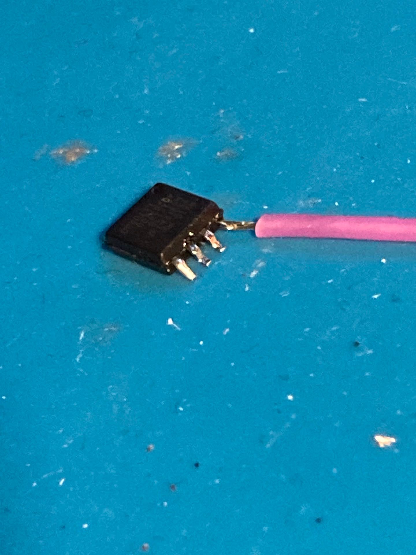
Some sources mentioned, I could just attempt to lift the VCC pin (pin 8) to isolate the chip’s power supply from the motherboard. So I tried just that, using my soldering iron and pointy tweezers. I lifted it a little bit, and tried the alligator clip from the programmer again. Nothing. Maybe I didn’t lift it enough, so I tried again.
And I broke the pin.
Will it work? (Spoiler: No, it won't.)
Classic. But since even with the pin lifted, I still couldn’t read it properly. I ordered two new Macronix MX25U12873FM2I-10G chips and decided to start fresh.
While waiting for the new chips, I thought: “If one chip is broken and I’m already waiting for replacements, why not desolder the backup chip and try flashing it?”
Success (Finally)
I desoldered the B_BIOS chip (doing it for the first time, it was scary), placed it in my SOP8-ZIF adapter with the 1.8V module, and… it read perfectly! I dumped the chip contents twice, compared them – identical. The chip was fine; the motherboard circuitry had just been interfering with the programmer. Now I needed to flash a new BIOS onto it. But wait – should I compare my dumped BIOS with the generic Gigabyte BIOS using UEFITool to check for board-specific data?
UEFITool Analysis
I analyzed both the original dump and Gigabyte’s F53i BIOS. As I suspected, both files were structurally identical – same size (16MB), same NVRAM location, same overall UEFI structure.
The main difference was in NVRAM content:
Original BIOS: Used/configured NVRAM with actual system state, boot configuration, memory training data, custom settings, XMP profiles
Cool, that means I can safely flash the Gigabyte BIOS directly. There was NO board-specific calibration data to preserve. Everything in the original NVRAM would be regenerated on first boot.
The Final Push
I flashed the F53i BIOS, verified it twice, and resoldered the chip to the M_BIOS position on the motherboard. This was a fun challenge – to get the pins and pads aligned, but also drown it in solder flux so that there was no solder blobs that should short or bridge the pins.
Installed the CPU, RAM, and graphics card. Powered it on.
Nothing. The POST display just showed 00, and the boot didn’t proceed.
Of course. What was I thinking? Did I do something wrong along the way?
Then I remembered: BIOS upgrade path. The Gigabyte site recommended specific steps for upgrading from early BIOS versions, especially when jumping to F40 and beyond.
At this point I went back to UEFITool to see the original BIOS dump and check the version there – it was F5, a very early BIOS from 2017-04-07.
Ha, my 2700X didn’t premiere for a whole another year after this was released!
The Right Way
I ordered two brand-new chips. When they arrived, I flashed one with F20 BIOS (Pinnacle Ridge support), soldered it to the B_BIOS pads, and…
IT BOOTED.
IT'S ALIVE!
I ran Windows 10 PE from a USB stick and executed the EC Firmware Update, as it was recommended before upgrading past F31/F40. Then I followed the proper upgrade path:
F20 → F31 → F40 → F53i
Everything worked perfectly. I repeated the process for the second chip on M_BIOS. Same upgrade path, same success.
Lessons Learned
In-circuit BIOS programming on modern motherboards is a pain. Desolder the chip if you can.
Early X370 boards are ridiculously picky about RAM. BIOS updates help, but you need the right starting point.
BIOS upgrade paths matter. You can’t always jump from ancient BIOS to the latest version directly – especially on AMD platforms with AGESA updates.
Two computer repair shops gave up on this board. Sometimes persistence (and a soldering iron) wins.
DualBIOS™ isn’t magic. If both chips have incompatible/outdated BIOS versions, you’re still stuck.
The motherboard now lives again, ready to be a backup workstation or NAS. My friend was happy. I learned a ton about BIOS chip programming and AM4 platform quirks.
And somewhere, two repair shop technicians are wondering why they didn’t just try flashing the BIOS chips.
Total cost: Two BIOS chips (~PLN 20), a CH341B programmer with a SOP8-ZIF adapter (~PLN 50), and many hours of stubbornness.
Result: One fully functional motherboard and a new blog post.